Editing Geometries
Geometries in GPlates
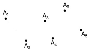
The geometries which GPlates handles are point, multi-point, polyline and polygon. Certain types of features contain different geometries, for example: a volcano uses a point to represent its position; a multi-point is used to represent a field of points which all have the same properties; an Isochron uses a polyline to represent its centre-line; and a basin uses a polygon to represent its outline.
Point
A point is the most basic form of geometry in GPlates and the basis of all other geometries.
Multi-point
A collection of points that move as one.
Polyline
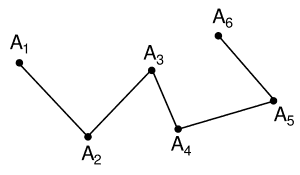
A series of lines drawn end-to-end, forming an open polygon. It is assumed that the lines are non-intersecting. Sometimes in GPlates the direction of a polyline is important, when determining the properties on either side of the line; for example, one side of a subduction zone represents the subducting slab, while the other represents the overriding plate. The direction of a polyline is determined from the "start" of the polyline (the first point digitised) to the "end" of the polyline.
Polygon
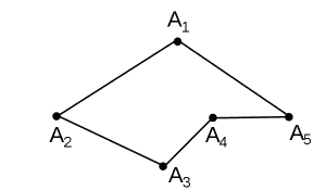
A series of lines drawn end-to-end, forming a closed shape. It is assumed that the lines are non-intersecting.
Geometry-Editing Tools
The geometry-editing tools are Canvas Tools and can be found in the Tool Palette. To begin editing geometries it is first necessary to either:
-
Have started digitising some geometry using one of the three digitisation tools (Polyline, Multipoint, Polygon).

|
The Split Feature Tool
 works only on a feature selected with the Choose Feature Tool
 .
. |
Each geometry-editing tool is only enabled if there’s enough geometry for it to make sense to use that tool. For example, if you are digitising a polygon and have digitised three points so far then the Delete Vertex tool will be disabled because it doesn’t make sense to have a two-vertex polygon (polygons require three or more vertices).
 Move Vertex Tool
Once you have selected a feature, its properties will appear in the Current Feature Panel. Little dots will appear on the chosen feature geometry, representing the vertices and can be positioned to a new location. The changes made to the geometry are immediate and there is no need to press an "Apply" button.

|
This tool is useful for correcting mistakes in the features' geometry. |
 Insert Vertex Tool
If the current geometry is a polyline or polygon, when the user clicks on a line, a new vertex is inserted at that position on the line. The line will highlight yellow when the mouse is close enough to the line to insert a vertex. This vertex may then be dragged to a new position, using the move vertex tool.
The Insert Vertex tool can also be used to extend a polyline at either end. If you move the mouse such that it is closer to one of the endpoints than any other point in the polyline then you can see visually that a subsequent mousse click will extend the polyline by one line segment. The same applies to a polygon except the two endpoints are now the first and last vertex of the polygon and the line segment between the last and first vertex will be replaced with two line segments that link the first and last vertex with the inserted vertex.
If the current geometry is a multi-point, a new point will be created at the click-position.
 Delete Vertex Tool
If the current geometry is a polyline or polygon, when the user clicks on an existing vertex, that vertex will be deleted. The vertices on either side of the removed vertex will now be connected directly, creating a new polyline or polygon. In the case of multi-point geometry, when the user clicks on an existing point, the point will be removed.

|
Note that if a vertex (i.e. point) is removed from a multi-point geometry which contains only two points, it will become a point geometry. |

|
It is invalid to remove a vertex from a single point geometry. In order to remove the geometry entirely the feature will have to be deleted. |
 Split Feature Tool
When the user clicks on a line the clicked geometry will be split at that point into two geometries. The line will highlight yellow when the mouse is close enough to the line to perform a split. After the split the original feature will contain one geometry and a new feature will be created to contain the other geometry. Both features will have the same properties and will only differ in their geometries (and their feature ID which is their uniqueness identifier).
In the Feature Properties Dialog
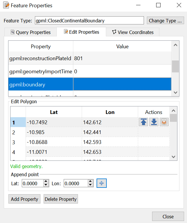
The controls for directly editing the coordinates used by geometry appears as a table with Lat, Lon, and Actions columns. Click a row of the table to select it, and the following action buttons will appear:
-
Double-clicking an entry in the table lets you edit a coordinate directly.
- The Valid Geometry line will indicate if the coordinates in the table can be turned into correct geometry. It will indicate an error if there is something invalid about the coordinates, such as a lat/lon of 500 or similar.
-
The "Append Points" spin-boxes are designed to be a convenient means of data entry, if you need to enter some points from a hard copy source.
- Click in the Lon to start entering new coordinates. Type in a lon value, press TAB, type in a lat value, press TAB (to move to the "+" button), press SPACE to activate that button. The new coordinate line will be added to the table, and GPlates will prepare to receive the next line of input.
-
Selecting a property from the table and selecting Delete will delete the property from the feature.


